L298N MOTOR DRIVER CONTROLLER DRIVER
Required EquipmentĪssemble the circuit as shown in the connection diagram below.Īrduino UNO with L298N Motor Driver and DC Motors
L298N MOTOR DRIVER CONTROLLER HOW TO
Now, as we have seen how to control the dc motor through the motor driver, let us do a demonstration by showing you how to control two DC motors using this driver. Interface L298N DC Motor Driver with Arduino UNO

Motor B is also controlled in a similar way. For backwards motion, IN1 should be HIGH and IN2 should be LOW. In order for motor A to spin forward, IN1 should be LOW and IN2 should be HIGH. Otherwise, when both the inputs are LOW (ground) state or both are in HIGH state then the motor stops. IN1 IN2 Motor Action 1 (HIGH) 1 OFF 1 0 (LOW) Backward 0 1 Forward 0 0 OFFĪs seen from the table, whenever one of the inputs is in a HIGH state (5V) then the motor will spin. The table below shows the logic signals required for the appropriate spinning action for motor A. IN1 and IN2 control motor A’s spinning direction whereas IN3 and IN4 control motor B’s spinning direction. Through these input pins we can determine whether to move the dc motor forward or backwards. The speed control pins labeled ENA and ENB on the module, control the speed of the dc motor and turn it ON and OFF. One type controls the speed and the other type controls the direction of the motor. There are two types of control pins found at the bottom right side of the module. Let us now see the details behind controlling the dc motor through the L298N module. Controlling DC motors through L298N Driver Module Motor A having voltage between 5-35V, will be connected through these two terminals.

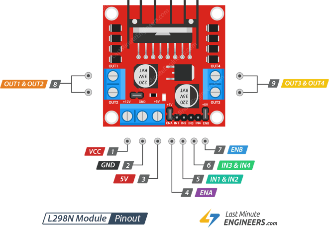
ENB This pin controls the speed of the motor B by enabling the PWM signal. They control the spinning direction for that particular motor. IN3 & IN4 These are the input pins for motor B. IN1 & IN2 These are the input pins for motor A. ENA This pin controls the speed of the motor A by enabling the PWM signal. If jumper is intact, then it acts as an output pin. Will be used only if the 5V enable jumper is not intact. 5V This pin supplies the power (5V) for the internal circuit (L298N IC). It is imprinted with +12V on board but can be powered between 6-12V. Pin Name Description VCC This is the pin which supplies power to the motor. Let us now look at the pinout of the module. The table shows some specifications of the L298N motor driver module: Driver Model L298N Driver Chip Double H-bridge L298N Maximum Power 25W Maximum Motor Supply Voltage 46V Maximum Motor Supply Current 2A Driver Voltage 5-35V Driver Current 2A Size 43x43x26mm L298N Module Specifications PinOut Note: If the jumper is connected, do not supply power to both the motor power supply input and the 5V power supply input. If the power supply is more than 12V, make sure the jumper is not intact and supply 5V power through the pin separately. The 5V pin in this case acts as an output to power the microcontroller. If the motor power supply is less than 12V then we will power the module through the voltage regulator. Keeping the jumper intact, means the 5V regulator is enabled. The module also has a 78M05 5V regulator which is enabled through a jumper.

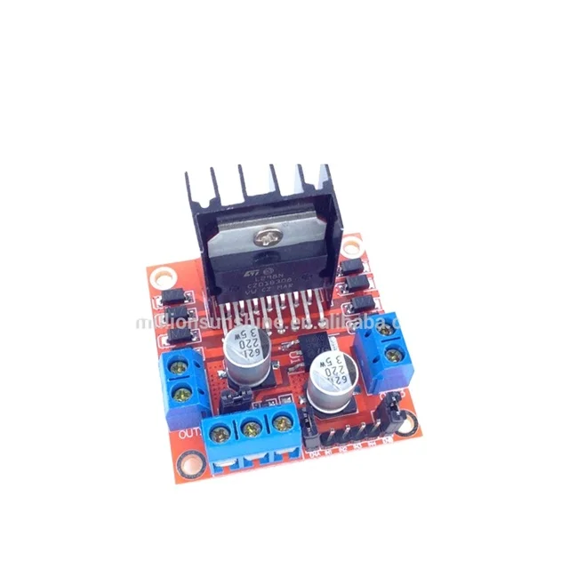
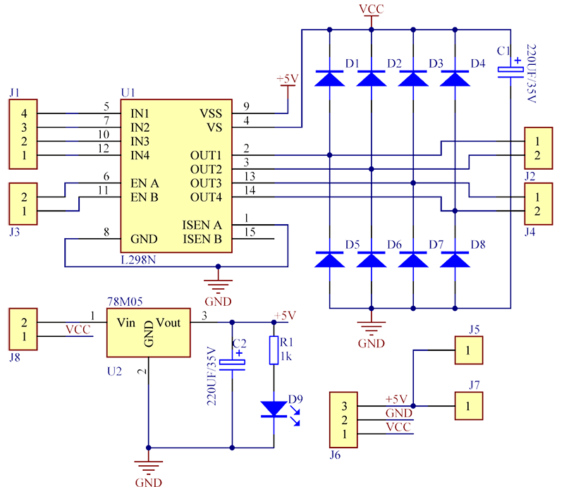
It is a dual-channel H bridge motor driver which can be easily used to drive two motors. The L298N Motor driver IC is powerfully built with a big heat sink. The diagram below shows all the components consisting inside the module. The L298N motor driver module consists of an L298N motor driver IC, 78M05 5V regulator, 5V jumper enable, power LED, heat sink, resistors, and capacitors all combined in an integrated circuit. This module is mainly used in robotics and in controlling dc and stepping motors. Thus, it is perfect for two-wheeled robots.

It is widely used in controlling robots as we can connect up to four motors at once but if we want to control the speed and direction as well then it allows two motors to be connected. The L298N motor driver module is very easy to use with Arduino and relatively inexpensive as well. Demonstration L298N Motor Driver Module.Arduino Sketch: Controlling DC Motors using L298N Motor Driver.Interface L298N DC Motor Driver with Arduino UNO.Controlling DC motors through L298N Driver Module.


 0 kommentar(er)
